5. CellML models in OpenCOR
For a better understanding of the models OpenCOR is used in order to visualize the behaviour of the different key parameters of the model.
5.1 The Beeler Reuter model
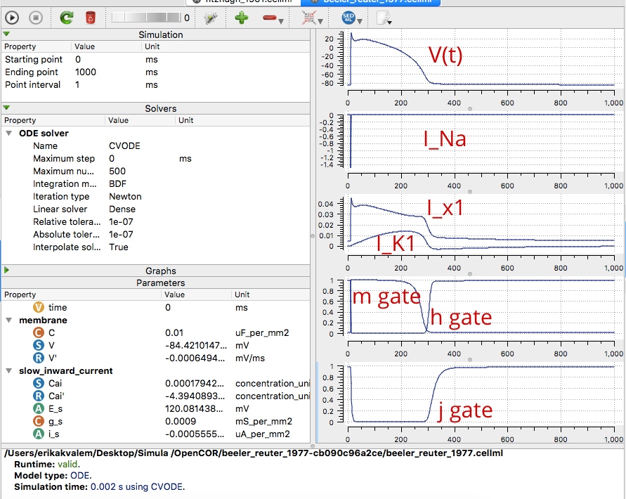
The following screenshot refers to the Beeler Reuter model run by OpenCOR. There are four plots regarding the different parameters.
The first one shows the voltage dependence on time V(t) also known as action potential. It can be distinguished the depolarization, plateau and repolarization phases of the action potentail of a cardiac cell.
The second reffers to the fast inward current (INa). This one has a very brief downward (inward current) spike that is triggered when the membrane voltage reaches around -70 mV. This is caused by the big increase in sodium channel conductance (gNa(t)). This is related simultaneously with the fourth plot; the opening and closing of the m and h gates.
The third plot shows the time dependent outward current IK1 and the time independent outward current Ix1.
The fourth plot gathers both the m gate and the h gate. The opening of m gate coincides with the spike from the fast inward current (INa) seen in the second graph. The m gate is open during the plateau and is closed when the h gate opens.
The last plot refers to the second slower inactivation gate j. This is a special characteristic of this model since the Hodgkin and Huxley does not include this variable. The total ionic current in the Beeler-Reuter model is given by four currents, and the model uses eight variables. [16]
5.2 The Fitzhugh Nagumo model
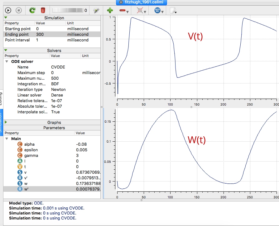
The following screenshot refers to the Fitzhugh Nagumo model run by OpenCOR. There are two plots regarding the different parameters.
In this case, since this model is an Empirical model which aims for a larger spatial and temporal scale only the V(t) voltage dependence on time and the W(t) recovery variable are plotted.
The first plot shows the Voltage dependence with time V(t). Comparing it with the second plot (recovery variable W(t)) it can be seen that depolarization occurs when the recovery variable is at its minimum.When the plateau is happening the recovery variable increases until repolarisation. It reaches the highest value just before going into this phase.
This helps the V(t) to recover in a progressive way until the threshold voltage is achieved again and a new Action potential is triggered. [17]
Paraview visualization:

This image shows how the AP changes along with the time. The initial value matches with the red colour and changes to white and blue during the action potential development representing the drop and different ups and downs of the morphology of the AP curve.
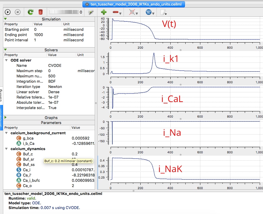
5.3 The ten Tusscher, Panfilov, 2006 model
This model is slightly more complex than the ones previously mentioned. It uses 12 transmembrane currents listed here:
-
Fast Na+ current
-
L-type Ca+2 current
-
Rapid delayed rectifier K+ current
-
Slow delayed rectifier K+ current
-
Inward rectifier K+ current
-
Transient outward K+
-
Plateau K+ current
-
Na+-Ca+2 exchanger current
-
Na+-K+ pump current
-
Sarcolemmal Ca+2 pump current
-
Background Na+ current
-
Background Ca+2 current.
From those currents some have been represented in the screenshot below (The action potential, K+ current, L-type Ca+2 current , background Na+ current and Na+-K+ pump current).
The interpretation and relation of the graphs is out of the scope of this page. However it is relevant to get an idea on how complex and complete this models can get, trying to simulate reality as much as they can. [18]
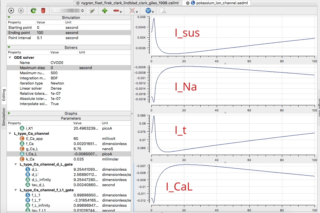
5.4 Nygren 1998 cell model
The following screenshot refers to the Nygren 1998 cell model run by OpenCOR.
The graphs refer to the ionic current waveforms during AP. INa is the first to respond to depolarizing stimulus pulse (delivered at time=0.1). INa activates rapidly and therefore there is a large transient inward current. This will generate the upstroke in the initial phase of the AP.
In the depolarizing phase It, Isus and ICaL are also activated. It, Isus reach their peak faster than ICaL resulting in a bigger magnitude. This leads to rapid repolarization dominated by It. Since time of inactivation is bigger for ICaL the net current is gradually dominated by it.
At the plateau phase of the AP there is a balance between Isus (and remaining It) repolarizing and ICaL depolarizing.
When ICaL inactivates, Isus dominates and togheter with rectifier currents (IK1,IK,r, IK,s)the cell AP goes back to resting potential. [19]
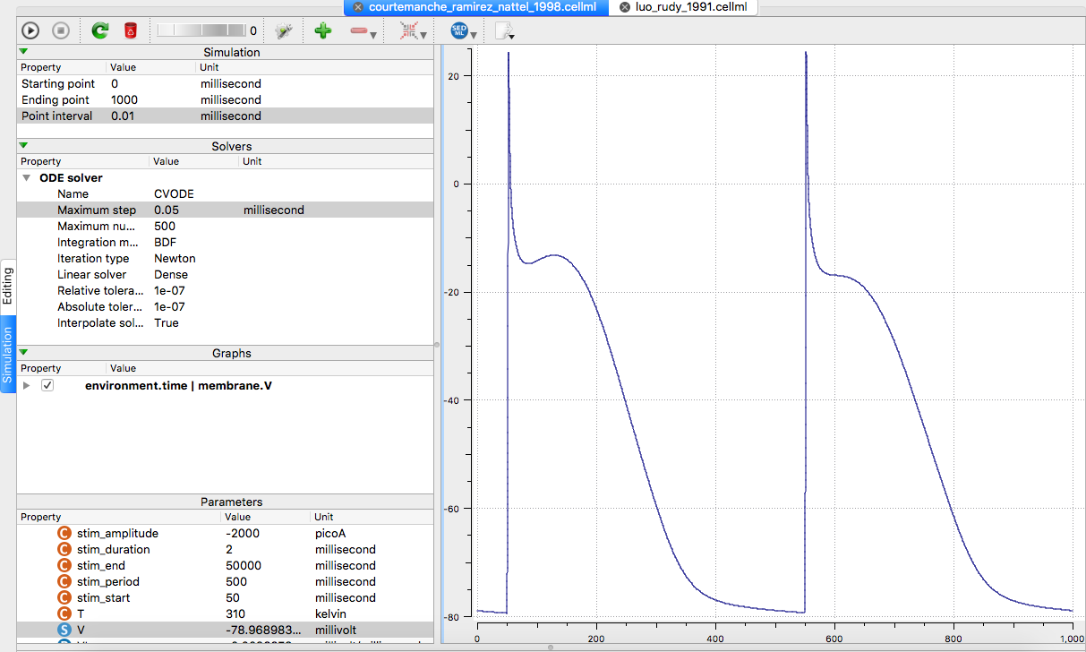
5.5 Courtemanche 1998 cell model
Behavior of the model action potential. It can be seen the control model action potential from the Courtemanche model. This model shows a spike-and-dome shape. This gif has been created out of the Courtemanche paper.
The action potential is initiated by the INa (Phase 0).
After that, repolarization produced by the transient outward current (Ito) follows (phase 1).
Rapid Ca+2 dependent inactivation is the next process (phase 2).
After that Ito and ICaL inactivation occurs, causing slight depolarization of the membrane. This is the main cause of the dome morphology (phase 3).
Due to this, there is a net inward current that is countered by slowly activating outward Ik leading to slow repolarization. (phase 4)
The final phase is slow late repolarization caused by a balance between deactivating Ik and time independent Ik1 together with opposing inward current generated by the Na+/Ca+2 exchanger. (phase 5) [20]
OpenCOR representation of the action potential. For this representation specific values for the paraeters point interval and maximum step were found. In this case these values are: Point interval = 0.01 Maximum step = 0.5
As it can be seen the same spike-and-dome shape is reproduced asabove.